How Deep Is Your Wub? - Finally Done
Note: The majority of this post was written back in September 2018, but some of it written in October 2019. Just assume what you're reading is from 2018 unless stated otherwise.
Over the past 4 months I've been working on my first synth. It hasn't been my first DIY project, but it's been the first project where I've made circuits from scratch rather than from kits on PCB. Note: None of the circuits I've come up with myself, but I've made small modifications throughout to most of them to suit my needs. I'll be sure to credit the creators when relevant and link you to the documents, so anyone can use them for their own purposes.
The synth, in short, has a 12-key keyboard, two oscillators, two LFOs, a low pass filter, tube distortion and a multi-fx unit. This project was many projects in one. Eight to be exact. Let me attempt to break it down. I'll try not to go into too much detail as I can see this post potentially taking as long to write as the project did to make (lol, it did), but if you'd like any extra info on how I did something, feel free to reach out.
THE OSCILLATORS
Both of these are the Look Mum No Computer 'Simplest Oscillator' circuits which were was originally discovered/designed/researched by Kerry D. Wong. I'm reading more and more recently on forums of these being a fairly temperamental circuit and that people are having to go through ten or so transistors to get them oscillating. Some have suggested that it's perhaps that's the manufacturer, which I'd assume as it wasn't really the case for me. I initially built the oscillators using 2N3904 transistors manufactured by Multicomp and then again using SS9018 transistors manufactured by On Semiconductor. More often then not these transistors oscillated in their reverse avalanche mode. I highly recommend, from my experience, to use the SS9018 transistors from On Semiconductor. (update 02/10/19: be quick though, these just got announced as EOL)
I should also note that the schematic for the circuit is incorrect. Most people build the oscillator from the veroboard layout (which IS correct), so it's not really an issue, but it is confusing when troubleshooting the circuit if it doesn't work first try. I've made an updated version of the schematic for reference.

My amended version of LMNC's Simplest Oscillator schematic.
I started with the 2N3904 transistors as that was the only oscillator design LMNC had out at the time (video). They start oscillating at ~12V. I had no bench top power supply at the time, so I powered the circuits with two 9V batteries in series. Running one oscillator off the power supply worked fine, but once I started running two I found that raising the pitch of one oscillator would lower the pitch of the other. I never quite figured out why, but some lovely helpful people in forums believed it may have had something to do with batteries having high internal resistance. ¯\_(ツ)_/¯
After roughly a month into sweating over different ways to get these oscillators to work, LMNC released a Part Two of the Simplest Oscillator circuit. It uses the exact same circuit design as the initial circuit, but with a SS9018 transistor which oscillates at ~8.2V. This oscillating voltage worked much better than 12V as it meant that I easily run everything off of 9V guitar pedal power supply instead of mucking around with a power booster. Also, the awkward interaction between the oscillators changing the pitch of each other was far less present. Still there, but much less noticeable.
I had a few digressions from the original circuit, but the only one worth mentioning was that I hooked the capacitor points on the circuit up to a DP3T switch with different value capacitors, so that each oscillator had somewhat of a 'range' switch. 10µF for high, 33µF for medium and 47µF for low.
THE KEYBOARD
After gaining a very vague understanding of how electricity works I dreamt up this idea for a simple keyboard, that in my mind was going to be amazing. In the end there were far too many factors at play and not enough knowledge in my head to make a functioning keyboard that would also be in tune. The design of the keyboard was intended to be somewhat of a take on the old stylophone circuits that get sold at DIY electronic stores like Jaycar, except without an annoying stylus and with pushbutton switches instead. I came across Ray Wilson's MFOS Mini-Controller. I copied his values of the resistors (100 Ω) on the keybed and hooked it up to one of my oscillators. To my surprise they worked quite well excluding the tuning on the final 3-4 notes which I ironed out with some random trim pots I had lying around.
Where it started to fall away from my original idea was when I introduced the second oscillator. The resistor values no longer gave a chromatic scale and the oscillators wouldn't track pitch in the same way. Then when I added a tuning pot to each oscillator the tuning range became displaced even more so. In the end I swapped the resistors for 1K trim pots and basically threw the idea of a tuned keyboard out the window. Could have probably worked around this with the knowledge I have now, but in the end it didn't really matter. I wasn't going to be playing ear blistering solos on this thing anyways.
THE FILTER
This circuit I used a design by Eric Archer. This is great sounding filter and I was really happy with the results. It has a pretty wide centre frequency range of ~40Hz-12kHz and you get a nice bit of oscillation on the resonance. The downside - soldering it to pad-per-hole perfboard is not an easy task. Small price to pay for a pretty decent low pass filter.
THE TUBE
This circuit I once again got from LMNC, but it's not one of his designs. It's called the Valve Caster and designed by Matsumin, but the below diagram is drawn by Beavis Audio. This site is unfortunately down and from the sounds of it has been down for a while (update 02/10/19: IT'S BACK UP!). I ended up building this one pretty much to spec to the diagrams, except for changing the 1µF capacitor on the tone pot to a 47µF capacitor as the 1µF wasn't really rolling off as much tone as I'd like. I probably could have gotten some better distortion by changing the values to some of the other components. Something to keep in mind for next time.
If you're interested, there's a version of the Valve Caster appropriated for eurorack audio levels and voltages called The Safety Valve.

THE FX
This entire section of the synth was part of a kit from MOD Kits DIY called The Suspended Chime. It's basically a Chorus and Chorus/Delay guitar pedal that runs off what they call a "Digital Sound Effector" named the BTSE-16FX. Sounds pretty boring, huh? But where it got fun is when I started poking around with it. The BTSE-16FX is actually a multi-FX DSP module with one of its intended applications to be used within karaoke units (lol). It's got a range of fairly vanilla effects from reverbs and delays to choruses and a flanger. The module has four switch inputs (pins 9-12) which when they receive 3.3VDC they register a 1. 0VDC and they'll register a 0. The module reads this binary data to determine what effect you would like it to process. The original design utilised a DPDT switch to toggle between chorus and chorus with delay. Swapping the DPDT switch out for four individual SPST switches on each on the modules switch inputs allows you to access all 16 of the modules effects. Just wire the 3.3V to the centre lug of the switch and any of the outer lugs to the pins to the DSP module.
Here's a link to the datasheet for the BTSE-16FX if you're interested.
Note: most of the rest of this post was written over a year after completing 'HDIYW?' and close to a year after starting the post. Some things I've forgotten how I did them. Other things I have an even better understanding of how I did them. Ya win some, lose some, riight?
THE LFOS
I've already put up a fairly in depth post about the LFO circuit I used in this synth. Click here to check it out. The summarised version is; I built 2 of these dual-wave LFOs. The outputs are fed to some homemade vactrols to control the pitch of the oscillators and the cutoff of the filter. Switches on each of the oscillators and the filter let you choose between either LFO 1, LFO 2 and of course no LFO. I also added a little switch that feeds oscillator 1 into oscillator 2. This could have come out better as at some settings (e.g. when LFO 2 is quite high) LFO 2 also feeds into LFO 1. Didn't notice until it was all boxed up, so I decided to leave it and call it "CHARM".
THE PENTAGRAM
I wanted this section to be a random demonic FX section that would have no explanation of what each effect was and mess with the user. This was the very last section I completed on the build and was super fun. It was kinda akin to circuit-bending, except I was doing it to something I made myself. It was all very last minute and fairly spur of the moment. I don't remember how I've wired all the SPST buttons up, really... Here's what I can remember:
Tube distortion feedback loop - This is pretty simple. One pin of the button to the input and the other to the output. It's super loud an obnoxious, but it's probably my favourite of the 5. If you muck around with the tone, gain and volume controls you can actually get it sorta musical in the end. It sounds super gritty. Kinda like power-tearing the longest pair of jeans in history.
Filter feedback loop - This is pretty similar to the tube distortion feedback loop. One pin of the button to the input of the filter and the other to the input. This can also be pretty loud and obnoxious. You can also muck around with the resonance, tone and mix controls with it on. When you have the resonance way up it kinda sounds like a radio scanning frequencies.
Pop! - I'm not sure what I'm doing here. I think I'm just discharging a capacitor somehow to the audio out. It's pretty silly to be honest and probably not a great idea.
Even bigger POP! - I'm pretty sure this is the same as above, but even more stupid.
Oscillator 1's weird LFO mod - In this one I'm also not very sure what I've done. Basically this sounds like it accentuates the affect of the LFO on the oscillator's pitch. BUT, only oscillator 1 and only if you're using LFO 1... I'm not really sure what I was thinking here, but hey, it was getting pretty late in the piece and was making all kinds of weird decisions.
THE BIG BUTTON
This just engages the (for lack of a better title) drone mode. It's wired up just before the highest key on keybed, so it's always playing the highest tuning and disengages the keybed. It has an LED, which isn't super visible. I'm not 100% sure (because it's been over a year now), but I'm pretty sure the voltage being sent to the LED is taken from the outputs of the two oscillators and being sent straight to the non-inverting input of an op amp in a non-inverting amplifier config. I wanted to just sum the outputs of the oscillators and get a visual representation of that, but in the end I made a happy mistake that turned out way cooler. The light actually ends up responding to the phase of the two oscillators. So when they're most in phase it's at its brightest and least in phase, lowest, yada yada yada. I could have definitely added a resistor in the feedback path to make the light brighter. At the time I didn't realise I was dealing with voltages so low. Maybe one day when I'm feeling brave I'll open this thing up and add that one resistor. Below is the schematic of how it's wired up. Click here to view the simulation.

Not pictured: How I had to hack the micro switch in the arcade button to be latching because I couldn't find any latching micro switches anywhere. Highly not recommended.
FINAL THOUGHTS
I'll never build anything with a keybed or actual, proper tuning until I understand how an exponential converter works.
You always want your LFO to be faster and slower at the same time.
Always get a bigger box.
In some ways I feel like I've been quite loose with describing this project as a synthesizer, but really what is a synthesizer anyway? An electronic musical instrument, right? In the end I felt 'How Deep Is Your Wub?' fulfilled both those criteria. It may not be as musical as other synths, but still musical to me. That musicality just tends to be thrown in with a large serving of unpredictability.
There's a severe lack of schematics for the modifications that I've made for a few reasons. Because the context for most of these tweaks are so niche that I can't see it being of much use to anyone else, Because figuring out these solutions is half the fun! However, if my descriptions aren't enough for I completely understand and highly recommend you to reach out if you'd like some more in depth explanations. Or maybe a half-cooked schematic?
Omg. Really? You've made it this far? But, why? Thanks for reading if you actually did. If not, I totally understand. I'll reward you with some random pics from the build.
Early breadboard of the 2 oscillators and 2 dual-wave LFOS. So droney! So flashy!

The CAD file. Not shown is the layer with all the component bodies that would be hidden behind the panel. I put this together on QCAD to make sure everything would fit on the top of the box. Dealing with such limited space it's a MUST!

Hand-drilled and scuffed up. Ready for a paint. This was before I thought about printing a CAD-made drillplot (which I had). Each hole was measure out by hand. What a waste of time. I know better now! It came out pretty damn good though. Although, the last 4 holes for the keybed make me die inside.

Painted up. How about that pink! So good.
Arcade button light in action!

Hand-painted labelling all done.

GUTS! I think this is the oscillators, LFOs and keybed. I had no idea how much of a tight fit this would be.
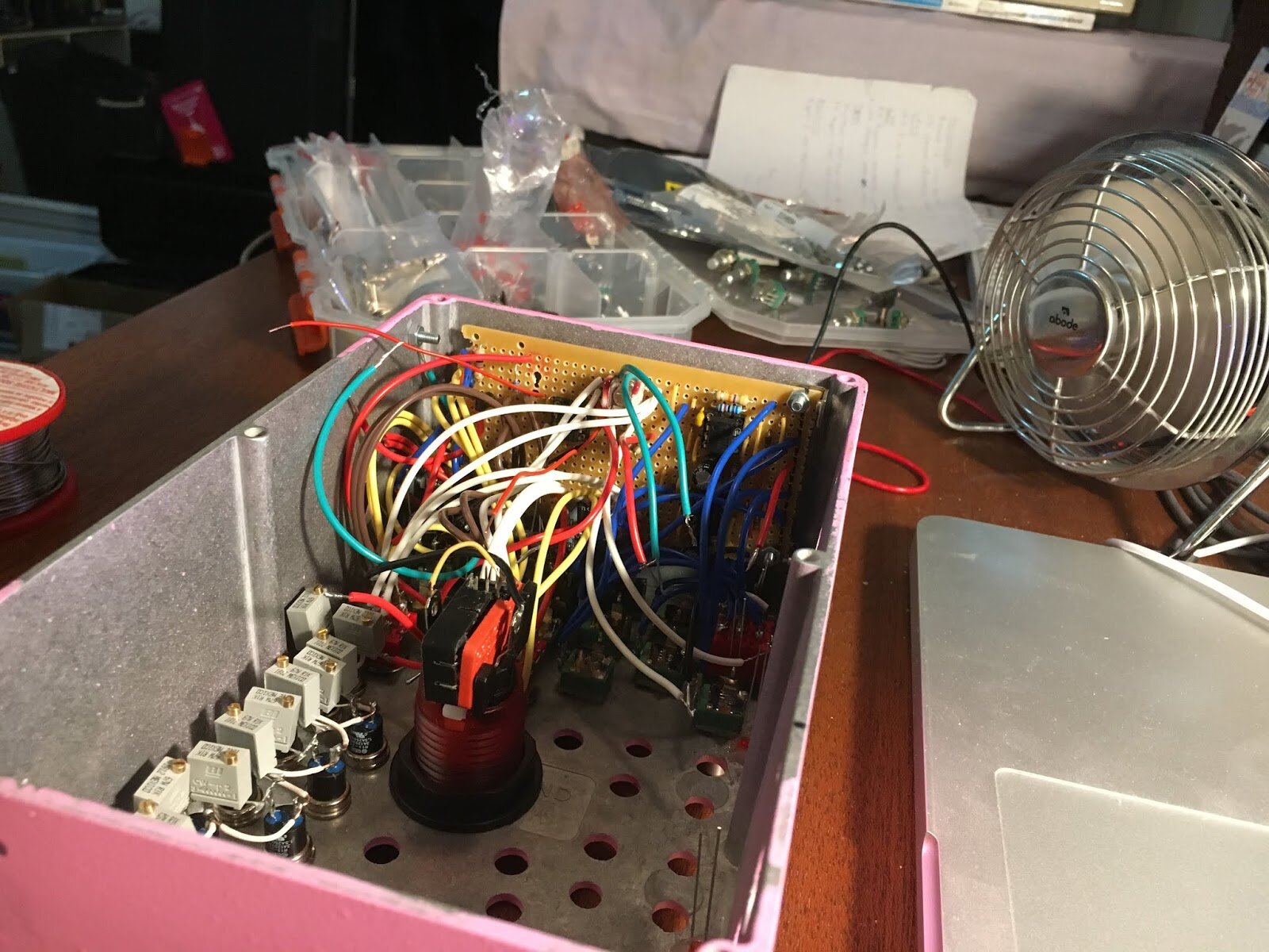
GUTS #2! Same stage. DIFFERENT ANGLE!

Time to squeeze that filter in there somewhere. I really only got it to fit at the very end. I think I may have had to off some veroboard before screwing in the back. lol
It's making noise! Filter, Oscillators, LFOS and keybed fitted.

I think I fit the tube distortion in sometime before this photo. All that stuff hanging out is the Multi-FX section.

ALL DONE! See at the very top of this post for a quick demo of some of its sounds.